- 您现在的位置:买卖IC网 > Sheet目录472 > MAX2163ETI/V+ (Maxim Integrated)IC TUNER ISDB-T LOW IF 28TQFN
ISDB-T 1-Segment Tuner
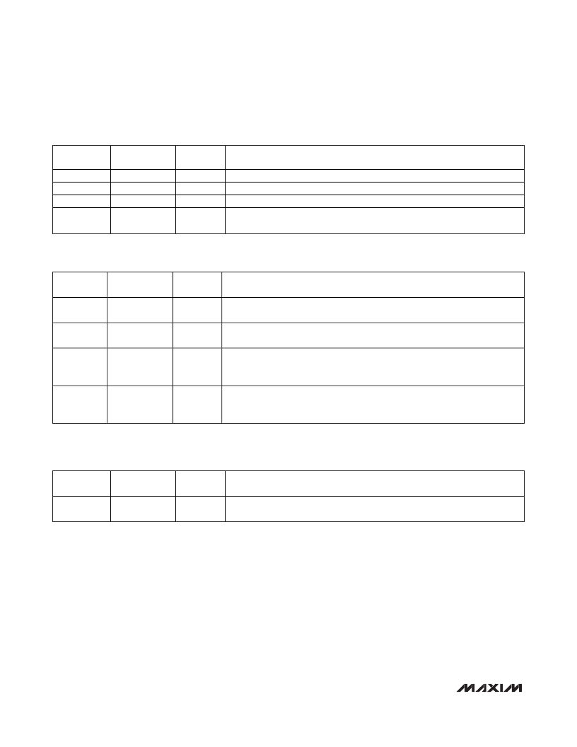
Table 12. STATUS Register (Read Only)
BIT NAME
X
ADC[2:0]
VCP[1:0]
PWR
BIT LOCATION
(0 = LSB)
7, 6
5, 4, 3
2, 1
0
DEFAULT
1,1
—
—
1
FUNCTION
Unused
Indicates the 3-bit ADC conversion of the VCO tuning voltage (VTUNE).
Reflects the charge-pump current setting, when CPS = 1.
Logic-high indicates power has been cycled. STATUS register read operation
resets PWR to 0.
Table 13. VAS STATUS Register (Read Only)
BIT NAME
VVCO[1:0]
VVSB[3:0]
BIT LOCATION
(0 = LSB)
7, 6
5, 4, 3, 2
DEFAULT
—
—
FUNCTION
Indicates which VCO has been selected by the VCO autoselect state machine. See
Table 5 for VCO[1:0] definition.
Indicates which sub-band of a particular VCO has been selected by either the VCO
autoselect state machine. See Table 5 for VSB[2:0] definition.
Indicates whether VCO autoselection was successful.
VASA
1
—
0 = Indicates the autoselect function is disabled or unsuccessful VCO selection.
1 = Indicates successful VCO autoselection.
Status indicator for the VCO autoselect function.
VASE
0
—
0 = Indicates the VCO autoselect function is active.
1 = Indicates the VCO autoselect function is inactive.
Table 14. Factory Use Only Registers (0B, 0C, 0D, 0E, 0F, 10 and 11)
BIT NAME
X
BIT LOCATION
(0 = LSB)
7, 6, 5, 4, 3,
2, 1, 0
DEFAULT
00000000
FUNCTION
Factory use only. Must be programmed to 0 upon power-up.
16
______________________________________________________________________________________
发布紧急采购,3分钟左右您将得到回复。
相关PDF资料
MAX2165EVKIT+
KIT EVAL FOR MAX2165
MAX2170EVKIT+
KIT EVAL FOR MAX2170
MAX2202EWT+T
IC POWER DETECTOR RMS 6-WLP
MAX2203EWT+T
IC RMS PWR DETECTOR 6WLP
MAX2204EVKIT+
KIT EVAL FOR MAX2204
MAX2205EVKIT+
KIT EVAL FOR MAX2205
MAX2209AEBS+T
IC RF PWR DETECTOR 4UCSP
MAX2209EVKIT+
EVAL KIT MAX2209
相关代理商/技术参数
MAX2163ETI/V+T
功能描述:调谐器 ISDB-T 1&3-Seg Low-IF Tuner RoHS:否 制造商:NXP Semiconductors 功能: 噪声系数: 工作电源电压: 最小工作温度: 最大工作温度:
MAX2163ETL+
制造商:Rochester Electronics LLC 功能描述: 制造商:Maxim Integrated Products 功能描述:
MAX2164E/D+
功能描述:调谐器 RoHS:否 制造商:NXP Semiconductors 功能: 噪声系数: 工作电源电压: 最小工作温度: 最大工作温度:
MAX2164E/D+T
功能描述:调谐器
RoHS:否 制造商:NXP Semiconductors 功能: 噪声系数: 工作电源电压: 最小工作温度: 最大工作温度:
MAX2164EVKIT+
功能描述:射频开发工具 MAX2164 Eval Kit
RoHS:否 制造商:Taiyo Yuden 产品:Wireless Modules 类型:Wireless Audio 工具用于评估:WYSAAVDX7 频率: 工作电源电压:3.4 V to 5.5 V
MAX2164SEVKIT+
功能描述:射频开发工具
RoHS:否 制造商:Taiyo Yuden 产品:Wireless Modules 类型:Wireless Audio 工具用于评估:WYSAAVDX7 频率: 工作电源电压:3.4 V to 5.5 V
MAX2165ETI+
功能描述:调谐器 DVB-H Tuner RoHS:否 制造商:NXP Semiconductors 功能: 噪声系数: 工作电源电压: 最小工作温度: 最大工作温度:
MAX2165ETI+T
功能描述:调谐器 DVB-H Tuner RoHS:否 制造商:NXP Semiconductors 功能: 噪声系数: 工作电源电压: 最小工作温度: 最大工作温度:
